- January 27, 2023
- 3DParts4U
- 0
What is gear ratio? It’s actually a simple formula that shows how gears can work together. I will show you how it works in this blog. Or if you want to see a more tangible example, you can watch the linked video!
A gear is designed to transmit movement to other gears. A set of gears will result in a specific gear ratio. To keep it simple, we will calculate the gear ratio between two gears only. So there’s one drive gear and one driven gear.
You can visualize those involute gears in FreeCAD by generating them on your screen. You can do that in the Part Design workbench. They must both have the same Module to work together. The Module is the unit that defines the size of a gear.
When positioning two gears, you can calculate the correct distance between them with the formula below. T is the number of teeth.
Module * (T1 + T2)) / 2 = (2.50 * (10 + 8)) / 2 = 22.5.
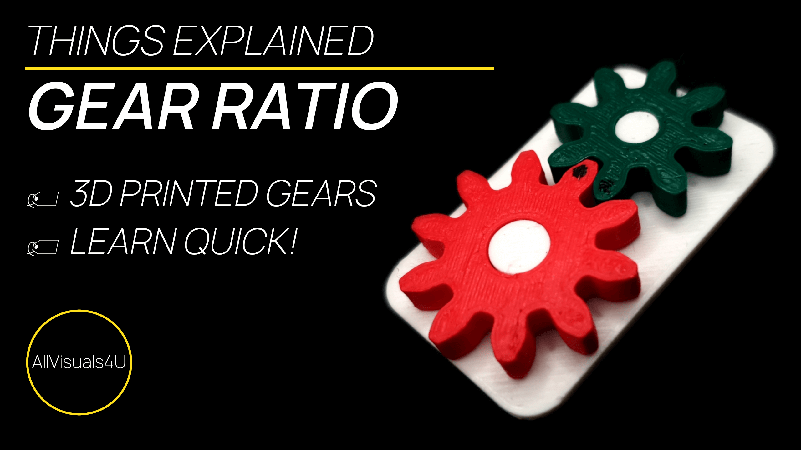
In this example one gear has 10 teeth and the other 8.
The gear ratio can be defined as: Teeth (green driven gear) / Teeth (red drive gear) = 8 / 10 = 0.8. A gear ratio lower than 1 means that it’s an overdrive gear transmission with a higher output speed. If the gear ratio is higher than 1, the output speed is lower than the input speed.
With FreeCAD you can generate involute gears in the Part Design workbench. A perfect free tool for simulating (3D printed) gears together.
If you want to see a visualisation of the steps above, the video below will show you how i generated gears in FreeCAD and 3D printed them to get a real example.
A video where i demonstrate how gear ratio works
So FreeCAD is a great tool for ‘creating’ your own digital gears. In addition to the linked video above, i made another on how to generate gears. Want to see more? Check out my other videos on the AllVisuals4U channel to learn more about 3D printing and design. I’ve been uploading a lot of tutorials and interesting videos there. Thank you!
